01
See the course
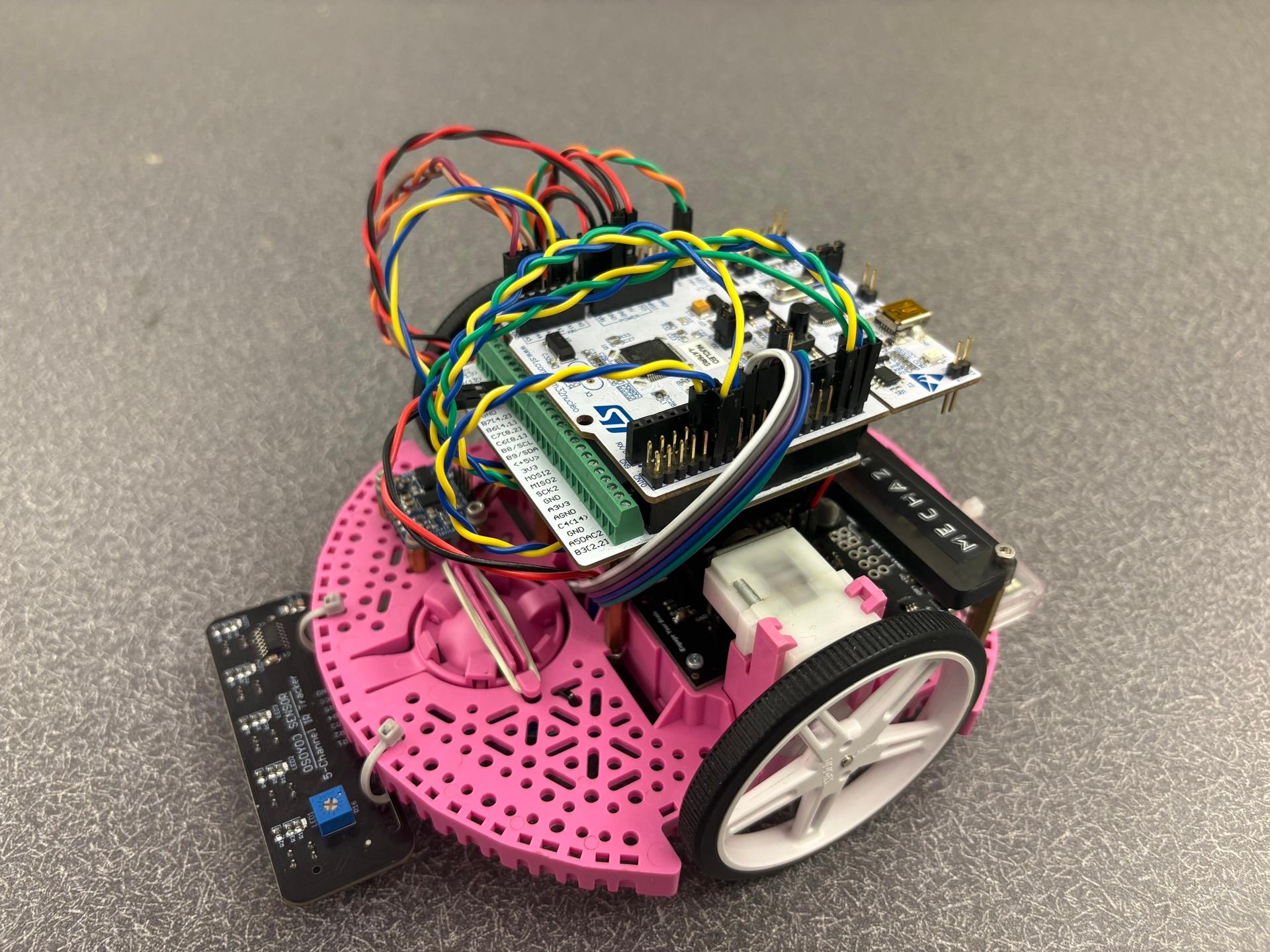
A five-channel IR array measures line position, while wheel encoders and the BNO055 IMU provide motion and heading feedback.
A two-wheel robot that follows lines, estimates its position from encoders and an IMU, detects a wall without a bump switch, and sequences its own route through a mixed-mode course.
05
scheduled tasks
20 ms
observer period
10
navigation stages
Final result
The final run combines ordinary line tracking with waypoint checks, precise turns, distance moves, and acceleration-based wall contact. The controller coordinates the transitions without a human selecting each mode.
System design
Controller
STM32 Nucleo L476RG
Firmware
MicroPython
Feedback
BNO055 IMU + dual encoders
Line sensing
5-channel digital IR array
Control
PI/PID + state estimation
Runtime
Cooperative task scheduler
Control architecture
01
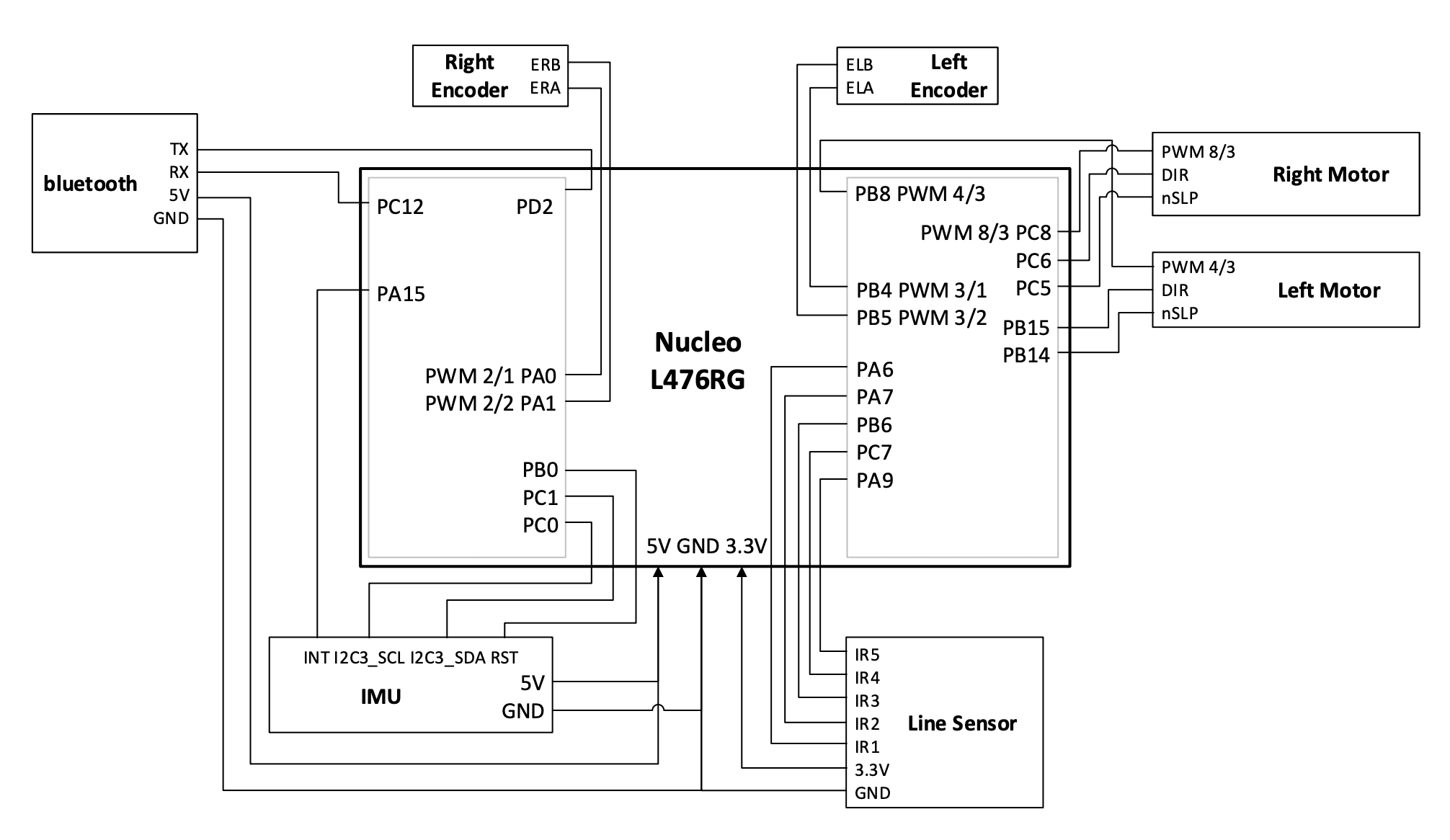
A five-channel IR array measures line position, while wheel encoders and the BNO055 IMU provide motion and heading feedback.
02
An observer running every 20 ms fuses motor effort, encoder position, IMU heading, and yaw rate into a live pose estimate.
03
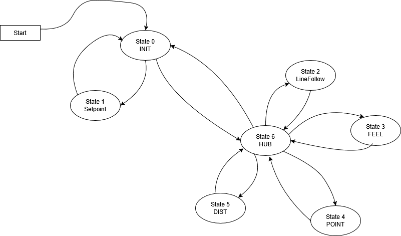
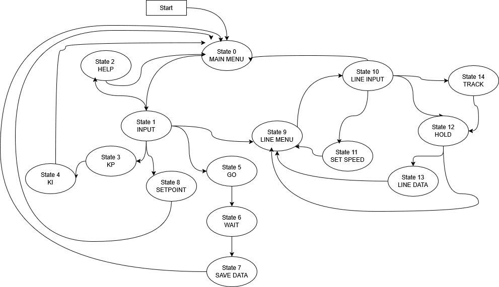
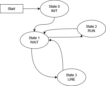
A finite-state controller switches between line following, heading control, distance control, and impact-based wall detection.
04
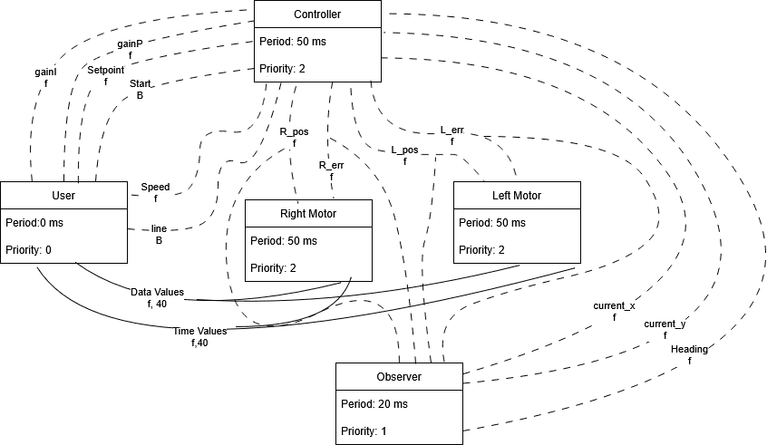
Independent 50 ms motor tasks apply the requested effort and report encoder data through shared variables and queues.
Test progression

Stage 01 / PI tuning
A circular course exposed oscillation quickly and made it practical to tune base speed, proportional gain, and integral gain before attempting the full route.
Stage 02 / autonomous route
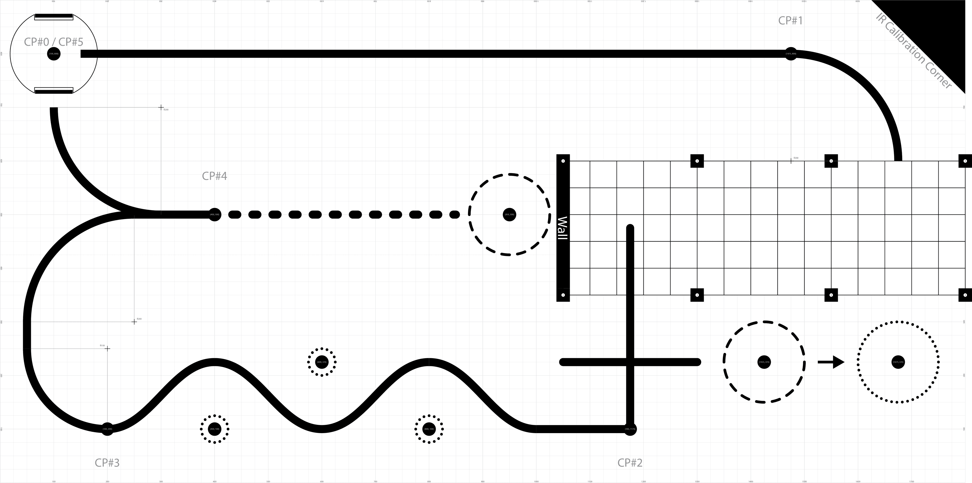
The course demanded long line segments, curves, a garage maneuver, wall contact, heading changes, and an unlined finish. A ten-stage hub sequenced each behavior.
Engineering lessons
The same motor command behaved differently as the battery discharged. A future revision would measure supply voltage and compensate the effort automatically.
The digital array was quick to integrate, but its five widely spaced sensors produced abrupt corrections. A denser analog array would give the controller a smoother error signal.
Instead of adding a mechanical switch, the robot detected a wall through acceleration. It worked, but hard acceleration could mimic an impact and required careful threshold tuning.
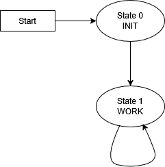
Finite-state design
Team credit
This project was created by Shafiq Amat and Max Soury. The firmware, testing, documentation, wiring, diagrams, and physical robot were the result of a shared team effort.